
INTERACTIVE MODELS
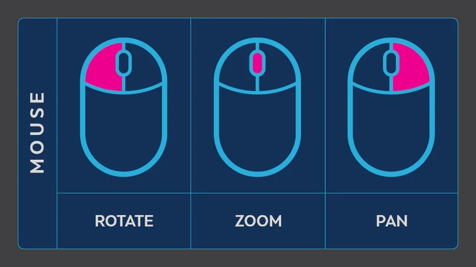
Our interactive models provide a unique look at some of the production equipment Hydrafab designs and manufactures. Below are the navigation controls for the models.

PRODUCTION MANIFOLDS
The production manifold is designed to accommodate the total production from all of the wells, and once the individual flows are combined in the manifold, they then pass on to the main separation train.
Where each flow line terminates at the manifold, there will be a valve isolation available, plus a check valve in order to prevent flow reversal back along individual flowlines.
In the event of problems arising within the system (i.e., effective boxing in of the manifold at both ends), the manifold can be depressurized to the flare system through a blowdown valve arrangement or relieved to the atmosphere and then drained for maintenance or other servicing.
FREE WATER KNOCKOUT
A free-water knockout is commonly called a three-phase separator because it can separate gas, oil, and free water. The liquids that are discharged from the free-water knockout are further treated in vessels called treaters. Once the hydrocarbon lines have gone through their respective manifold lines, it is then sent to the Free Water Knock Out (FWKO.) FWKO’s can be vertical or horizontal and are used mainly to remove any free water that can cause problems such as corrosion and the formation of hydrates or tight emulsions, which are difficult to break.
Where each flow line terminates at the manifold, there will be a valve isolation available, plus a check valve in order to prevent flow reversal back along individual flowlines.
The Free Water Knockout is designed to provide low-velocity flow when combined with a large water and oil interface area. It allows the maximum amount of water to settle down. With increasing demand, diverse manufacturers are presenting the vessel in a number of shapes and sizes to meet specific conditions and requirements. The degree of separation depends on the retention time, the density of the differential fluid, and the temperature of flowing fluids.
HORIZONTAL HEATER TREATER
The fluid from the FWKO is further processed through a heater treater. A heater treater is a vessel that uses heat to break oil-water emulsions so the oil can be accepted by the pipeline or transport. There are vertical and horizontal treaters. The main difference between them is the residence time, which is shorter in the vertical configuration compared with the horizontal one.
Flow enters the treater, where gas is flashed. The liquid falls around the outside to the vicinity of the oil-water interface. Oil and emulsion rise past the fire tubes and are skimmed into the oil surge chamber. The oil-water interface in the inlet section of the vessel is controlled by an interface level controller, which operates a dump valve for the water.
The oil and emulsion flow through a spreader into the back or coalescing section of the vessel, which is fluid packed. The spreader distributes the flow evenly throughout the length of this section. Treated oil is collected at the top through a collection device sized to maintain uniform vertical flow of the oil. Coalescing water droplets fall countercurrent to the rising oil continuous phase. The oil-water interface is maintained by a level controller and dump valve for this section of the vessel.
A level control in the oil section operates a dump valve on the oil outlet line regulating the flow of oil out the top of the vessel to maintain a fluid packed condition.
VERTICAL GAS SCRUBBERS
A vapor–liquid separator drum is a vertical vessel into which a liquid and vapor mixture (or a flashing liquid) is fed and wherein the liquid is separated by gravity, falls to the bottom of the vessel, and is withdrawn. The vapor travels upward at a design velocity which minimizes the entrainment of any liquid droplets in the vapor as it exits the top of the vessel.
VAPOR RECOVERY TOWER
A vapor recovery tower is a tall pressure vessel that is installed between the production separator(s) and the liquid storage tanks.
A Vapor Recovery Tower technically meets the standards of being a pressure vessel and thus is considered by the EPA to be process equipment. It is not considered to be a storage tank and is not subject to the Quad O Regulations.
VRT’s are engineered for proper retention time to allow gas to separate from the liquid and have no potential for liquid traps in gas vapor piping to VRU. Oil gravity feeds from the tower to the tanks, allowing no oxygen ingress and allowing vent gas modeling with a one to two psig separator pressure.
OIL & WATER STORAGE TANKS
Once the oil, water, and gas have been separated, it then flows to storage tanks, often grouped together, called a tank battery or a tank farm.
Here, the oil & water are stored until transported off-site.